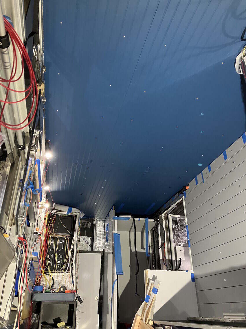
The ceiling design was of particular importance given my desire to retain as much headroom as possible. I’m 6’2″ (74″) and the module, with the existing ceiling completely removed, is also 6’2″. In bare feet, I can stand comfortably without having to duck my head. In any kind of footwear I have to tip my head to varying degrees, but as I don’t stand perfectly ramrod straight, this isn’t particularly problematic. I figure if I really want headroom I can simply step outside. Removing the old ceiling recovered a half inch of headroom as the builders had used a rigid foam insulation board in addition to the aluminum composite panel that made up the ceiling. Whatever I put in I knew I wanted as thin as possible.
Fortunately, the module was constructed with 2″ aluminum square tube, which meant there was room for insulation without cutting into my headroom. This space had previously been stuffed with a polyester batting. I replaced the polyester insulation with 1.5″ of mineral wool, and then sealed it with Reflectix and aluminum tape to create a vapor barrier. For the ceiling panel material I decided on beadboard, which measured 1/8″ thick. This was about the thinnest material I could find short of going with aluminum sheet. The old ceiling minus the foam board insulation was another option, but it was 1/4″ thick and full of various holes and rectangular openings for all the lights, IV hangers, antenna access, etc.


Conveniently, the module had four long aluminum plates welded to the ceiling frame running longitudinally (front-to-back) that would make a nice and level surface to fasten the beadboard to. Not so conveniently, like the ceiling, these plates were cut in various places to accommodate the IV hangers, vent mounts and lights. I had originally planned to use a combination of M6 bolts, rivnuts and fender washers to secure the beadboard, similar to what I did on the bunk wall. However, in this case, I couldn’t counter bore the beadboard to recess the fender washers as I had the bunk wall shiplap given it was a wafer thin 1/8″. This meant the fender washers would sit proud of the beadboard surface. Initially this seemed like a fair trade off, as they would add lots of surface area to support the ceiling. The downside being they would provide many opportunities for me to bump my melon. For this reason, I selected fender washers with a beveled edge.
The other consideration was spacing the fasteners such that they provided enough support to prevent the beadboard from sagging. Once I started laying out the positioning of the fasteners I realized that the fender washers might not be as necessary as I had initially thought. So it was time to build a mockup using a scrap piece of beadboard.


While the bolt-only option would be comparatively weaker than the fender washer, given the number of fasteners and spacing I decided that that would likely work fine and give me a flush ceiling with no head-gouging protrusions.
Next I had to make sure each bolt would have something behind it to anchor into, given the irregular layout of the aluminum plates in the ceiling. I also wanted all the bolts to be spaced as evenly as possible. I should also mention that I wanted to avoid the use of any adhesives to secure the ceiling in order to make any future maintenance or modification easier. This required creating a detailed drawing of the ceiling structure overlaid with the locations for all the fasteners.
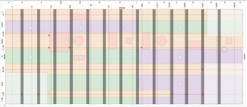
The above drawing shows the overall layout of the ceiling structures, looking up as if you were laying on your back. I wasn’t going to be putting ceiling panels above the built-in aluminum cabinet along the driver’s side so I left that off the drawing, which is why it looks abnormally skinny. The layout I came up with required four separate beadboard panels, denoted by the green and purple areas. Orange represents the aluminum plates I would be mounting to. The light red areas designate existing cutouts in the aluminum plate. The horizontal and vertical dotted lines designate rows of bolts and where they intersect indicates a proposed mounting point. The red dots are just there to remind me those particular points have critical spacing and I need to be extra careful. The large red square towards the rear is the 14″ x 14″ opening for the ceiling vent. While it does impinge on two mounting points, it has a plastic bezel that extends roughly 2″ around the opening. This meant that I could move those two mounting bolts an inch out of line and they would still be covered by the flange. The long, narrow grey rectangles are the aluminum frame-members and the blue circles are the puck light locations. The measurements along the margins denote the location of the fasteners both from the origin of the left-rear of the truck as well as the distance between each row. This latter measurement was to make sure the rows were somewhat evenly spaced. In short, I needed to locate the fasteners in the orange plates all while avoiding the red openings and grey frames and while trying to keep the mount points as evenly spaced as possible and ensuring the ceiling panels were adequately supported.
The only real problem area was the area in the middle of the ceiling where there were square, rectangle and circle cutouts grouped together, all three of which would impinge on anchor points. While I could have welded additional plates to patch these areas, the easier solution was to simply adjust the entire line of anchor points by roughly two inches forward to avoid those cutouts. Visually, it wouldn’t be a big deal, since I was more concerned about the bolt alignment front to back than side to side. I felt the eye would naturally pick out flaws alignment in that direction over the shorter side-to-side alignment.

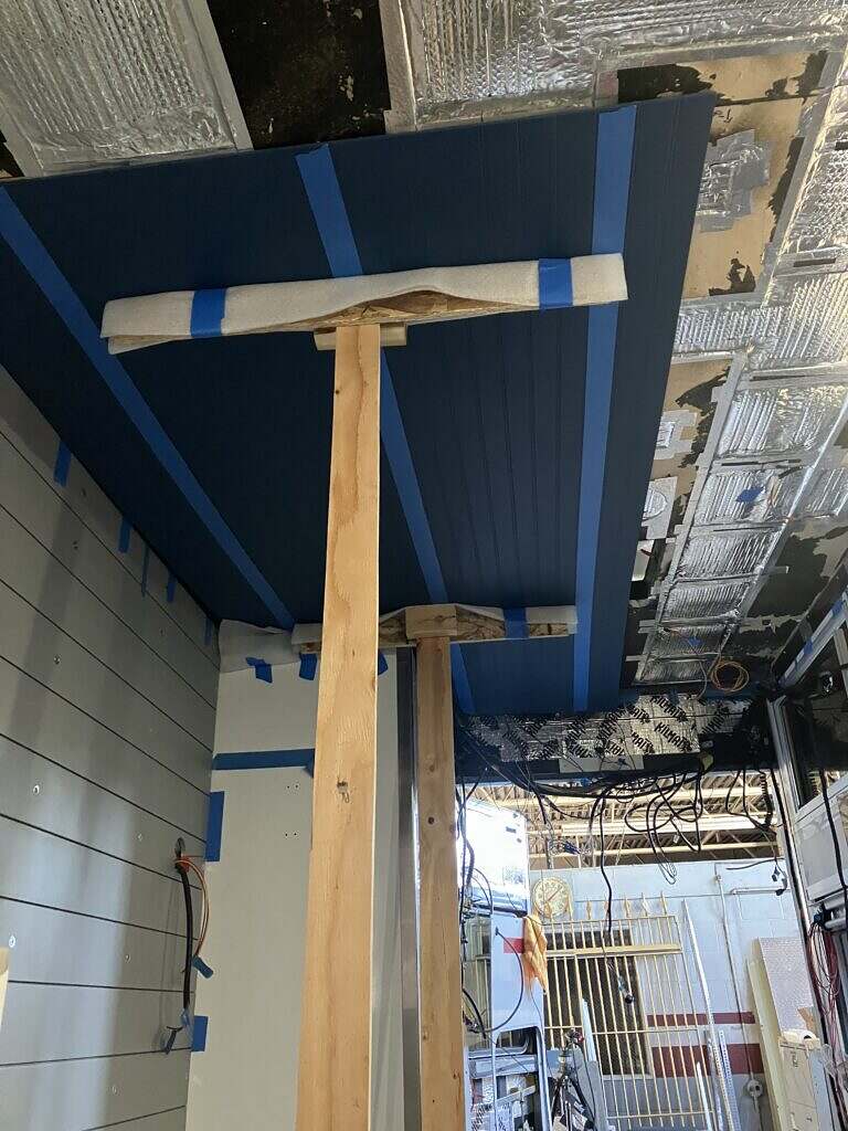
Fortunately, given the square construction of the module, fitting the ceiling panels was fairly easy as I didn’t have to deal with any curves at all. The only cutouts I had to make were to accommodate some wiring access in the forward part of the module, none of which would be visible anyway. By cutting the beadboard edges carefully along the “bead” the seam running from front to back is all but invisible. The seam across the width of the module was much more noticeable so I opted to use a plastic seam cover painted to match the ceiling. Because of the ridiculously tight tolerance between the panels I had to modify the seam cover in order to get it installed.
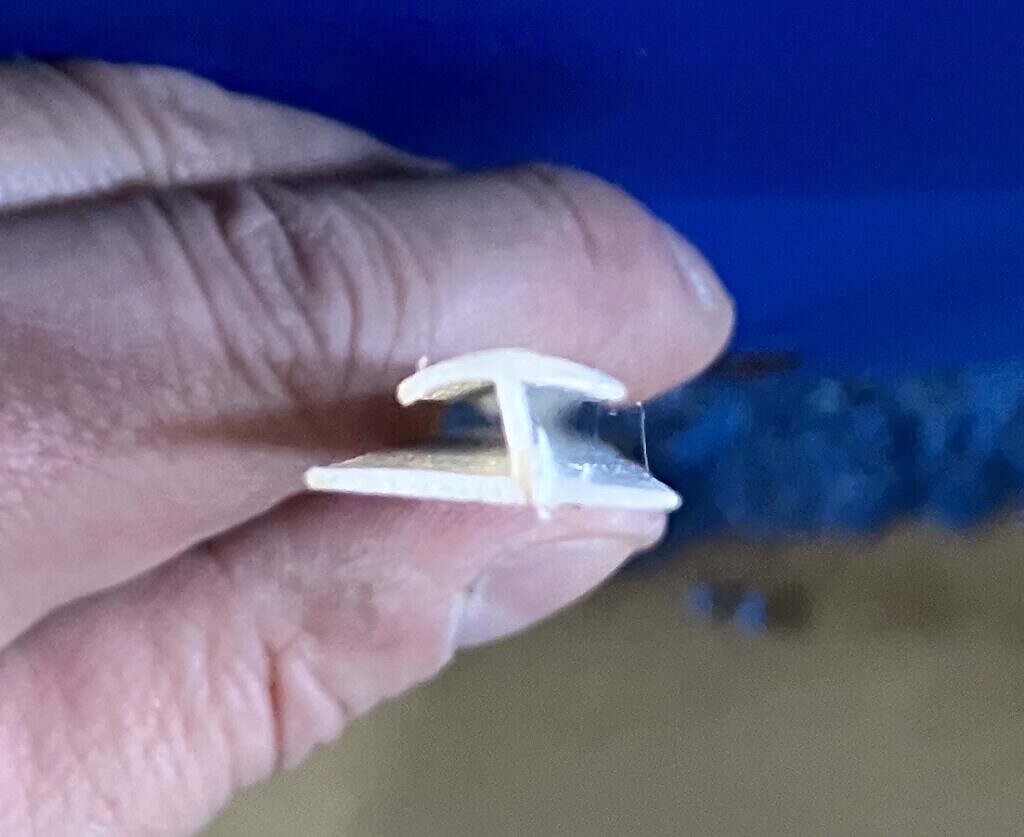
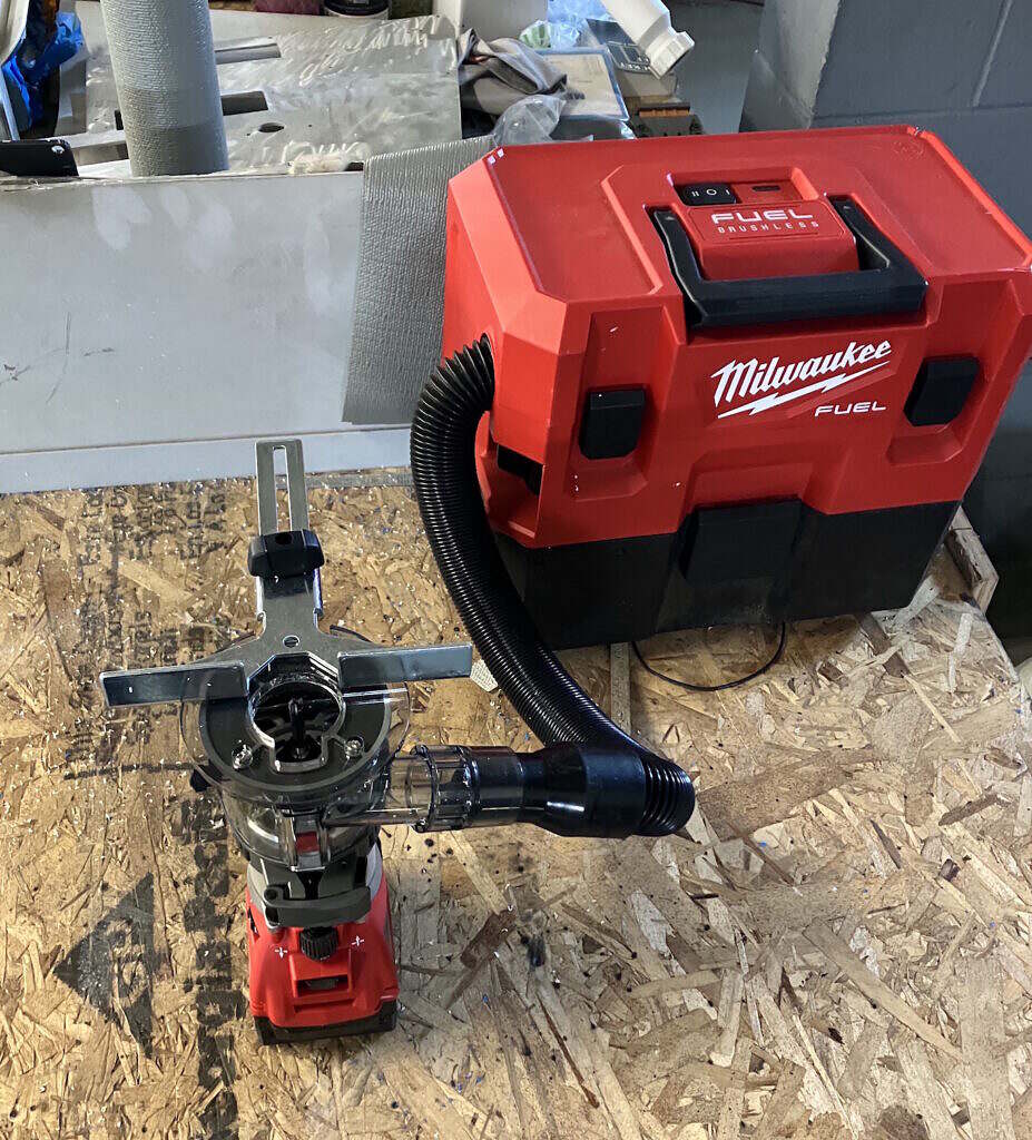
This cover piece was plastic and in order to fit between the panels, I had to trim one of the short, curved legs. In order to do this, I flipped my router over and used the edge guide to make a sort of makeshift router table.
Lighting
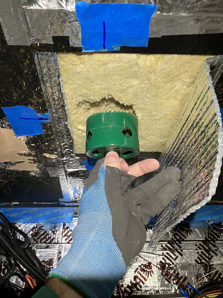
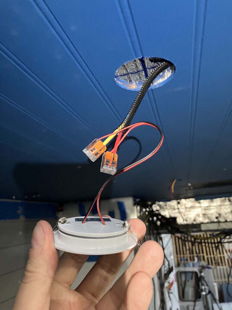
While the new LED puck lights were only 1/2″ deep, I wanted to provide a bit of a relief so they wouldn’t be pressed against the beadboard by the insulation and cause it to bulge outward. To accomplish this, I used an oversized hole saw to hand saw out a roughly 1/2″ thick plug from the mineral wool. I had no concerns about the lights getting hot as they are only 1.5 watts each.
The next problem I had to tackle was how to find the carefully positioned locations for each light on the beadboard. The obvious solution would be to simply transfer the measurements from the ceiling to the beadboard. However, this is problematic, at least for me, and I didn’t have a lot of confidence the resulting holes would line up. Instead, I bought a pack of tiny rare earth magnets, which I then taped to the center point of each light location before putting up the beadboard. Once the beadboard was secured I could take another magnet and it would snap to it’s match behind the ceiling. With a little back and forth movement of the magnet I could quickly confirm it was centered and make a mark for the hole saw. I then took the ceiling down, drilled the holes for the lights and that was all there was to it. I had perfect alignment of the holes with the points I had marked out on the ceiling.
I also put a fair amount of effort into minimizing the visibility of the seams between the four beadboard panels. The beadboard somewhat lent itself to this, since making cuts on the “beads” would naturally camouflage the seam. When I was done, I found my measurements had been so precise that I had to pound the two seams together with the heel of my hand to get them to fit.
The other major project for the ceiling was mounting the bunk cabinet. However, that will be detailed in a separate post.