Roof Ventilation
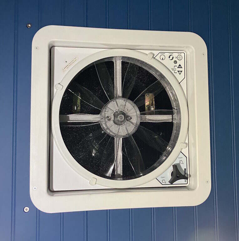
Early on I knew I was going to be putting in a roof mounted fan for ventilation. The gold standard for vans and RVs is the MaxxAir fan. They offer several models, though I went with the Deluxe, which includes a powered vent lift and remote. The Deluxe is also rain-proof when open and can be in use while driving. As luck would have it, a lot of the work was already done for me as the roof-top AC unit I had removed left a perfect 14″ x 14″ opening in the roof, which just happened to be the dimensions needed for the MaxxAir. I gather this is some sort of standard opening for rooftop vents/AC units.


The Coleman Mach AC unit that was on the roof originally worked fine, but it required far too much AC power to run off the house batteries and took up too much room on the roof. It also increased the truck’s overall height by 18″, including the massive aluminum diamond plate guard that was built around it. Whether I was keeping it or not, I had to remove both from the roof in order to fit through the garage door. While removing it I also discovered some evidence that it had leaked, either due to rain or perhaps accumulation of condensation from the unit itself. Besides the Coleman and regular cab AC, the truck is also equipped with a secondary heater and AC unit in the module. I was planning to rip that unit out to free up floor space, but a little research informed me that it was a fairly pricey unit, called a ProAir FrigiKing, designed specifically for emergency vehicles. It’s also looped into the engine’s coolant lines in order to draw heat from the engine and has a weather-proof condenser dual fan unit mounted under the truck. At present it runs off a dedicated AC compressor looped into the engine’s accessory belt. My plan, eventually, is to convert it to run off the house batteries in some way, though I’m not even certain if it’s possible at this point. If that doesn’t work out and I eventually do decide to put in a dedicated AC for the module, I’ll use a modern mini-split which would more efficient than the Coleman anyway, which is 14 years old.
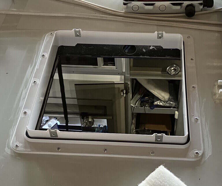
The first step in mounting the MaxxAir is to install a supplied rooftop flange, which is sealed with Dicor or Sikaflex and then screwed down. The fan unit itself, then screws to this flange and the interior is finished with a plastic trim ring that is cut to a depth appropriate for the thickness of your roof. It pained me to drill 16 new holes in the roof to accommodate the mounting screws, but they are all heavily sealed with Dicor, both above and below the flange, so I don’t think there will be any issues with water leaks.
I had previously run some 12 gauge wire to the opening so all I had to do was splice the positive and ground to the provided fan leads. The fan motor is reversible so it can switch between sucking or blowing at the touch of a button.
For the interior I made an additional modification to the plastic trim ring by gluing on thin galvanized metal bars to the inner face. This will provide an anchor point for the magnets I’m going to put in the blackout insulation cover I eventually plan to make.
Forward Bulkhead Vent
To compliment the MaxxAir fan, I also installed a manual trailer vent to the center front of the module where there had originally been an emergency strobe. This will allow air to circulate from front-to-back or back-to-front, depending on the fan direction, even with all the doors closed. This vent was designed for use in horse trailers, so it had rather large holes. To add some mosquito and no-see-um protection, I epoxied in some stainless steel screen before installing the vent.


Other Ventilation
In reading the riveting government regulations for ambulance construction, I learned one of the requirements is a certain amount of passive and active ventilation inside the module. This was originally accomplished by adjustable vents in the ceiling, which had 3″ ducts to a couple of nice stainless steel cowl vents on the driver’s side of the module. The aft vent was active in that it had a powered, in-line bilge fan to move air out. The forward vent was passive, having no fan. Since I got rid of the existing ceiling vents when I replaced the ceiling, I repurposed the bilge fan and rear cowl vent as an exhaust for the cabinet that will house my 3D printer. I also plan to add a second bilge fan and some 3″ diameter flexible tube to ventilate the utility cabinet using the forward cowl vent to aid in keeping the house battery bank cool.


Locker Ventilation
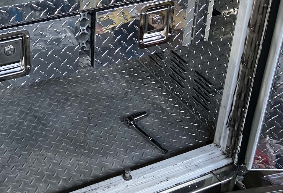
As we’re on the subject of air flow it’s worth noting that each external locker, save for the tool crib in the cab, is also vented through slotted vents located near the floor. I assumed these vents were mainly in place to equalize the pressure in the lockers when the doors are slammed shut, otherwise you risk popping the weather seals. Whether you know it or not, every car and truck on the road has some kind of vent for pressure equalization. This is usually one or more vents hidden behind a body panel or bumper fascia and it’s the reason your ear drums don’t pop when someone slams the car door with all the windows closed.
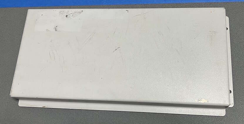
In each locker there is a plenum space behind each vent which directs the air up and over a vertical plate. From what I can determine this is designed to keep water spray and excessive dust from the road from easily entering the lockers. I discovered Locker D was slightly different than the others in that it also had a vent in the ceiling which is connected to the interior. This was no doubt for pressure equalization of the interior space and to provide a passive incoming airflow for the previously mentioned ceiling vents. This air flow created a bit of a problem in that Locker D’s vent is directly behind the right-rear tires, which would obviously kick up a lot of dust. This in turn allowed a lot of dirt to accumulate in Locker D. I didn’t notice this until I went to wash the interior of Locker D in preparation for the additional shelving I was installing. Unlike all the other lockers, which have diamond plate interiors, Locker D had some kind of high durability rubberized finish on the walls. When I scrubbed the walls I was rather surprised at the amount of grime which came off, leading me to reach the conclusions I did about the air flow. To avoid this in the future, I decided to fabricate a vent cover for the lower vent which would hold a replaceable furnace filter. The ceiling vent already had a nice looking diamond plate cover, which would also accommodate a cut-to-size furnace filter. For the bottom cover, I found the cover from the CPR seat air bag charge was a near perfect fit. I stripped the paint, used a 1″ hole saw to add a pattern of vent holes and polished it to a mirror finish. I also epoxied some stainless steel mesh screen to the inside face which would keep the polyester filter material from poking through the holes.