I’ve previously covered my power audit and the overall electrical design of the truck. That described how much power I think I’ll need and the various ways I’ll collect and store that power. The next step is power distribution.
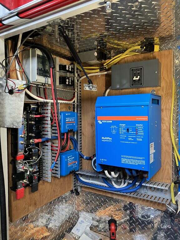
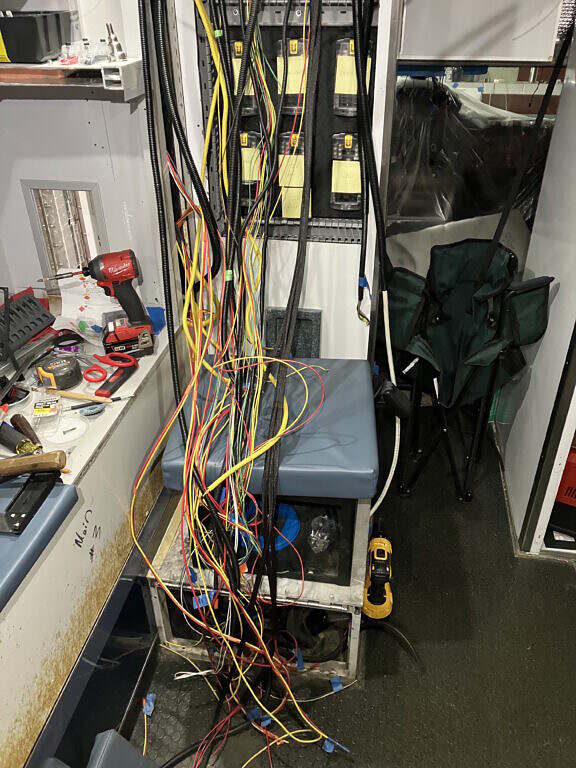
In the photo above, the various breakers for the solar panels and other DC sources are located at the top of the left-hand panel. The grey box on the top-right is the AC mains breaker for incoming shorepower. The large blue box is the Victron Inverter/Charger. On the left side, the upper blue box is the Victron MPPT solar charge controller and the lower is the Victron Orion DC-DC charge controller, which will charge the batteries when the truck is running. At the left, without a cover, is the Lynx Distributor and Battery Shunt. The batteries are not yet installed, but will be located in the area at the bottom of the image and be wired to the bottom of the shunt, which currently has red and black covers over the mounts.
I will have 350Ah (Amp hours) of storage available in the 24V battery bank, which is equivalent to 700Ah at 12V. The battery bank is comprised of four 12V 175Ah VMax Lithium Iron Phosphate (LiFEPO4) batteries wired in series-parallel to achieve 24V. In addition to 24V DC, the system will supply 12V DC and 110V AC through a 24>12V DC-DC step-down converter and a 3000W inverter/charger, respectively.
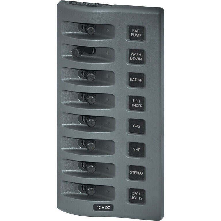
For my switch and fuse panels I’m using marine-grade components from BlueSea. They are a little more expensive, but they make high quality stuff and the sales engineers there were helpful when I needed questions answered.
Power for 12V DC loads will feed from the 24V battery bank through the Lynx Shunt and Distributor and into the DC>DC converter to be stepped down from 24V to 12V. From there the power will be split to feed to my inside control panel. Of course, appropriately sized breakers will be used between all these devices.
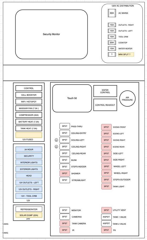
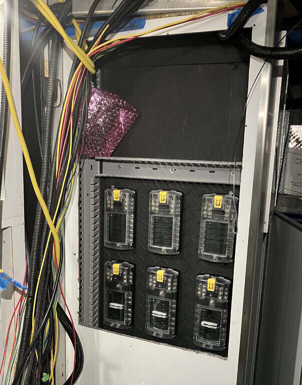
Here then, is the layout of my control panel. It will consist of a hinged front panel for mounting the various screens, controls and switches. Behind this will be space for mounting the BlueSea ST Blade fuse blocks and several busbars as well as raceways for routing wires.
My system uses a main/sub panel design. I will have two 12V, 8 switch Weatherdeck switch panels, one fused and the other non-fused. The fused panel will control individual loads such as the MaxxAir fan, cell booster and heaters for the battery bank and fresh water kegs. The fuses are standard blade fuses and can be sized appropriately for each load. The non-fused Weatherdeck switch panel will be for enabling/disabling sub systems via ST Blade Fuse blocks, which will then feed individual switched loads. For example, I will have one switch for my interior lighting, another for exterior lighting and another for the various components of my security system.
From the fuse panels the loads will be switched by individual switches, with things like ceiling lights or 12V outlets grouped as I felt made the most sense. Things get a bit (more) complicated here because I chose to have a rather elaborate switch system. In a couple cases, I wanted to be able to switch the load on or off from two locations. Additionally, while things like the interior lights would be obviously on or off, loads on the outside of the truck would not necessarily be visible when I’m inside the truck. While I didn’t want pilot lights on every switch, I did want them on those loads so I could quickly determine what was on or off with a glance at the panel. On the panel diagram above, illuminated switches are colored red.
My ceiling lights will be comprised of 10 LED puck lights in five separate circuits. There will be one circuit for the light over the side entry steps, another for the light in the pass-thru to the cab and the last two lights at the rear will be switched as a pair. The remaining six lights will be divided between the left and right side. These two banks of lights will also have dimmer knobs. Whew! As if that weren’t enough I also want to be able to switch the right-hand bank of 3 lights from either the control panel at the front of the module or my bunk. While it’s true the distance between these two points is approximately 6 feet, I could just imagine the annoyance of having to get up from bed just to turn off the overhead light. I only did this on the right-hand bank, because I anticipate this being the bank I use most of the time. Additionally, I will also be able to switch the rear pair of lights from the control panel or from a panel mounted on the rear doors.
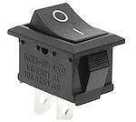
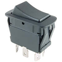
Switches come in dizzying array of variants based on what you’re switching and the features you want. I was mainly interested in rocker switches for my control panel, as opposed to toggle switches or push button switches. Obviously you need a switch that is rated for DC, can handle 12V and the amperage for each load it will switch. Switches are categorized by their “pole”, as in electrical pole, which determines how many devices they can connect to and their “throw” which determines how they switch those loads. The most common switch is the SPST (Single Pole, Single Throw) switch (this switch has two connections, which may be confusing, but remember that every DC circuit is made up of a positive and a negative.) This connects to one load and has an ON position and an OFF position. SPDT (Single Pole, Double Throw) switches still connect one load, but can switch two different ways. Then you have DPST (Double Pole, Single Throw) which could switch two separate devices at the same time or even multiple pole. However, even within relatively simple single pole switches, there are variants. ON-ON, ON-OFF-ON or ON-(ON) where the parenthesis designate it as a momentary switch, meaning the switch is only closed while it’s held. For example a SPDT (ON)-(ON) switch might be used for a motor connected to an awning. If you don’t have a limit switch in the system, then you don’t want the awning going too far out or in and so you only want it running while you hold down the button. Within those types you can also then have switches with various types of pilot lights and choices of what color, LED vs incandescent vs neon, etc. As if all that wasn’t complicated enough, then you have to choose the size of the switch; mini, standard or large, though this seems more an approximation rather than an industry standard designation. Round switches, square switch, rectangular switches, the options go on and on. Then you have choices for sealed or not and the shape of the rocker itself (concave, flat, etc.) I ordered a couple of cheap packs of a few different types if mini switches off Amazon, just so I could experiment and get it straight in my head how the circuits worked, using a couple of the LED puck lights as test loads. When in doubt, prototype. Switching a single load from two different locations is sort of like wiring a 3 way switch in your home, but different enough that I had to physically build the circuit to fully grasp it.
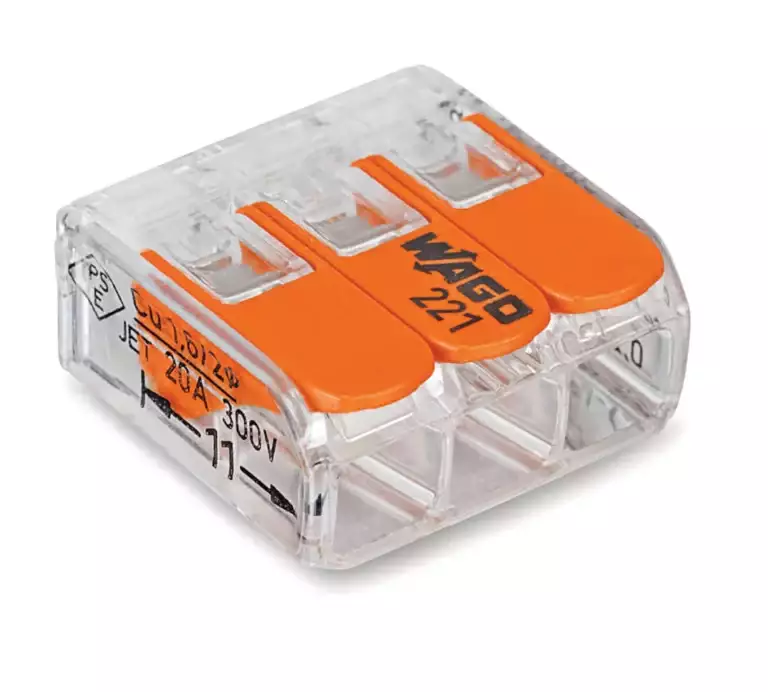
Throughout my wiring, both DC and AC, I’m using WAGO lever nuts rather than traditional twist on wire nuts. Wire nuts don’t work as well on stranded wire and with all the vibrations and temperature swings are not as reliable. WAGO connectors are available in different sizes and for various wire counts. They also have a recessed test port, which makes troubleshooting with a multi-meter convenient. They seem kind of delicate, but once I tested them, was impressed with how tight they held the wires. Lever nuts had been used in most of the rest of my truck, so I figured if it was good enough for the ambulance manufacturer then it was good enough for me.
The only place I am using twist on wire nuts is to terminate abandoned wires as I identify various things in the original ambulance wiring that I can disconnect. I’m using orange wire nuts for those terminations so I’ll know at a glance whether it was something I did or not. Again, this is probably overkill, but I’ve done enough network and phone system wiring and troubleshooting to know that when it comes to doing dumb shit, where there is a will, there is a way.
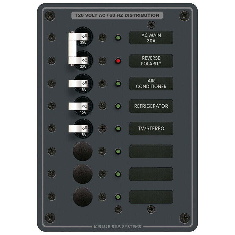
For the AC side of the system power will come either from the 30Amp shore power hookup or the 24V battery bank and then into the MultiPlus inverter/charger. The AC output of the inverter will go through a 30Amp mains breaker before feeding up to the AC breaker panel on my inside control panel. AC wiring is marine grade 10/3 from the shore power plug to the inside breaker panel and then 12/3 from the breaker panel out to the various loads. I selected a BlueSea AC Mains breaker panel with 6 breaker positions. The two 30Amp Mains breakers are redundant, but I wanted the ability to isolate the system from inside the truck or the utility cabinet, especially since here we’re dealing with 110V AC. I’ll also have the ability to switch the inverter on and off from the mobile app on my phone or on the inverter itself.
The question has been asked why I’m running full-length ground wires, where both the load and ground wires terminate in a fuse block or busbar, rather than using chassis ground, where the ground wire is simple grounded to the chassis near the load being supplied. While chassis ground is an acceptable method, and is what the ambulance manufacturer used, I have a couple reasons for not going that route. First, because the builders used chassis ground, I decided I wanted to keep my circuits completely separate. I used red wire for positive and yellow wire for negative so it’s easy to differentiate between my circuits and existing ambulance circuits. I’m also (mostly) adhering to ABYC marine electrical standards where full-length grounds are preferred. Finally it comes down to personal preference, I like knowing where every circuit is going and where it’s grounded. While full-length grounds can create an issue with voltage drop, which chassis grounding mostly avoids, I calculated the wire gauge for each circuit using it’s max load amps, a 3% allowable voltage drop and a 105C (221F) degree temperature rating (this is the rating for the insulation on the wire). There are also other factors that have to be considered, such as if the circuit will be in an engine compartment and how many other wires it will be bundled with. I was also extremely conservative when adding up total circuit length and rounded up to a larger wire gauge where the value fell in between two standard gauges. I standardized on 12, 16 and 18 gauge wire. So for example, if the calculation for a particular circuit called for 14 gauge, I used 12 gauge, etc. The concern with voltage drop and wire size is two-fold. When DC electricity travels through a wire it encounters resistance. The thinner the wire the more resistance, the more resistance, the more heat is generated. If you exceed the wires load carrying capacity you’ll melt the insulation, likely create a short and quite possibly start a fire. Voltage drop is a side effect of resistance. If you are supplying 12V at the source, but using too small of a wire gauge for the length of the circuit, there will be too much resistance and 12V wont be available at the load. Some devices don’t care about voltage drop or can tolerate a small amount of it, but other devices are extremely sensitive to it and will simply not function if they don’t get adequate power. When calculating the wire gauge to use for a particular circuit it’s important to remember that DC is a loop so you have to account for the entire distance the electricity has to travel. If using full-length grounds, as I am, that means multiplying the length of the positive wire by two. AC wiring also experiences some voltage drop, but it’s not as critical to account for it.